| Home |
| Misc. |
|
12-Oct-2015 Bertho Boman |
|
|
|
This is how simple it is. There are many types of sound trigger devices available for triggering cameras. Most of them are rather expensive and they have many other features. For some applications the variable delays and many features are not required. Here is a very simple way to create a sound trigger using just two components: A transistor and a diode.
First a little background: This unit is used to trigger a Nikon D700 but I expect that
the same circuit will work with most cameras.
Step 1: Microphone & Amplifier A very convenient and self-contained option is to use a Sound Pressure Level (SPL) meter. An old low-cost Radio-Shack 33-2050 meter was used for testing. They sell on eBay for $25 or less. 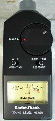
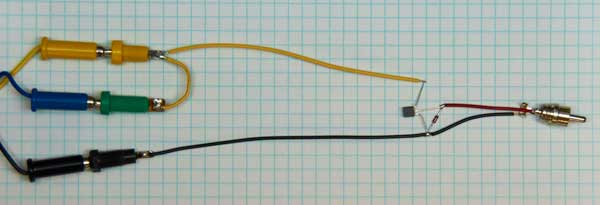
SPL Meter Step 2: Rectifier/Switch Connections Instead of showing a circuit diagram I temporarily connected the components as a visual design. 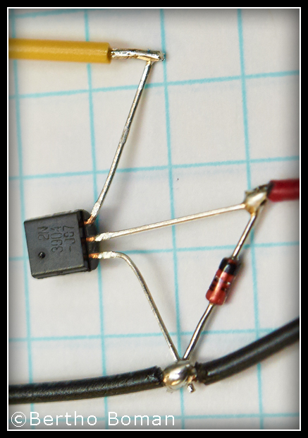
The Connections This just shows the basic connections of the wires and the diode to the transistor. For the final assembly it can be much smaller Only two items are required besides and wires and connectors:
The components are very non-critical. Almost any NPN transistor will work and any diode will be fine too. The black wires are "Ground" (common), the red one is audio input and the yellow trigger output. Step 3: The Camera Connections The easy, but expensive, way ($45) is to buy a Nikon MC-22A. The color coded banana plugs can be seen in the first photo. 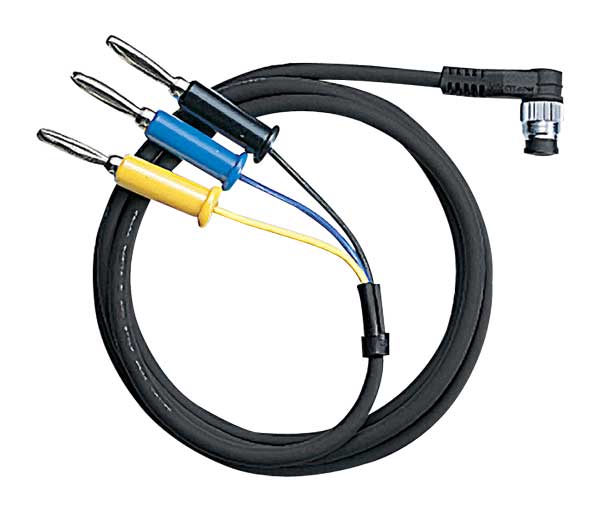
MC-22A The low-cost way is to buy an aftermarket remote trigger (about $5) and cut off the switch and just use the connector and cable. In that case you need to use an Ohm meter to find the correct wires since the color coding is unknown. 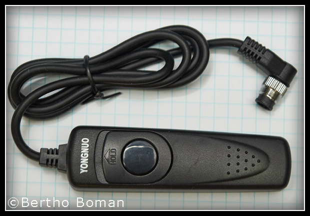
Brand X For camera pinout information see: www.vinland.com/Nikon_10-Pin.html Step 4: Camera Settings The camera should be set to manual focusing and the "awake" time "C2" should be changed to a much longer value depending on the application. Step 5: Final Assembly The two components can be hidden in any very small non-conducting box. They can even be left in the cable joint and covered by electrical tape. I wanted a very small device so I hid the components inside the Phono plug. 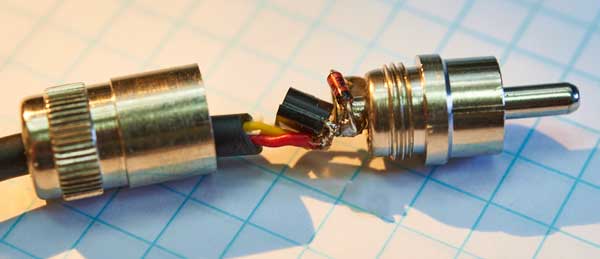
The parts are really squashed together 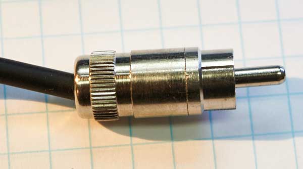
Finished and closed The space is really too small inside the connector so it is difficult to make it fit. If I have to make another one I will use surface mount components which would easily fit. Liability This circuit works fine on my system but any time non-brand name equipment is used there is always a possibility for errors or damages. In summary, use this information at your own risk. For more camera information and other projects see:
Bertho Boman
|