| Home |
| Misc. |
|
22-Aug-2008 Bertho Boman |
|
|
|
Introduction
They are used to find, for example, hole locations and size, reference planes and so on. They are also used to scan an object by repeatedly measure point by point on the surface and building a data file that can be imported into a CAD programs for further 3-D modeling. There are several commercial touch probes available that cost several thousand dollars, there are also some low-cost models for hobbyist for a few hundred dollars, and there are many descriptions on how to build one. I looked at many examples and some are beautifully made but often rather complicated and with many parts. I wanted a simple to manufacture one but still not giving up any accuracy so here is what I came up with and built one long night. Design Concept:
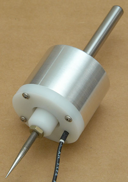
With today's CNC equipment it is easy to quickly calibrate a non-adjustable probe and to save that value for the future. Often that saved value is more accurate than a manually adjusted probe since it is very difficult to adjust it to be 'perfect". With that in mind and the desire to make it simple to build I split the design into four easy to make parts. Please see the pictures and the descriptions below: Construction Details: 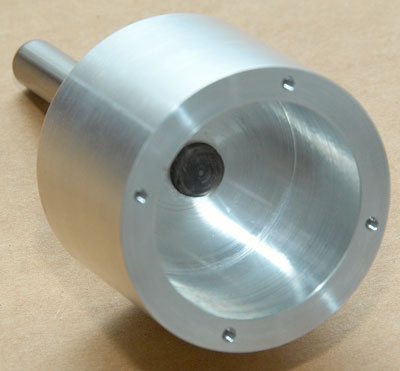
The main shell is made from aluminum, 50mm in diameter and 37mm long. It is hollowed out and also drilled and then reamed for a 3/8" (9.52mm) tooling pin that is permanently attached with high-strength Loctite. 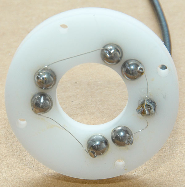
The ball holder plate is made from 7mm thick Delrin or if available some harder plastic. It has six holes drilled so the 6.35mm balls will be half submerged in the plastic. The balls are located on a 29mm circle. The adjacent balls are 7.35mm apart so the gap between the balls is 1.00mm. Before each ball is assembled, it is carefully cleaned, a small drop of soldering fluid (zinc chloride type, not rosin based) is placed on the ball and a very small spot of solder is flowed onto the ball using solid core or acid core solder. It sounds more difficult than it is. Practice on a couple of balls. Afterwards, carefully wash off any flux residue. Place a very small amount of epoxy or superglue on the inside edges of the holes and push the balls into the holes with the solder spot pointing away from the adjacent ball. The connection cable has been fed through a hole and it has been glued in place so it can not wiggle. Solder a very thin wire, (faster heat up time and easier to work with than a thicker wire), from the input cable, to each ball going around the center hole and finish on the other wire in the cable. It is easier to handle a long continuous wire than little pieces. Afterwards, just cut out the wire between the adjacent balls. Since the balls are in the plastic they cannot be heated too much or the plastic will melt. This time, place a small amount of rosin flux on the solder spot and lay the wire across it. Using a soldering iron with a reasonably sized tip that will hold the heat and set the soldering iron temperature to high, just touch the wire and solder spot for a fraction of a second. The solder will "instantly" melt and join the wire to the ball without significantly heating up the ball. Afterwards, wash off all flux residues. It is also possible and practical to pre-solder the wires to the balls before they are mounted into the plastic. By using soldered wires any question about contact resistance with a PCB used in some designs are avoided since the soldered connection is guaranteed to always be good and never marginal or intermittent. This type of construction requires minimum amount of parts and all the electrical connections are on one separate little plate. 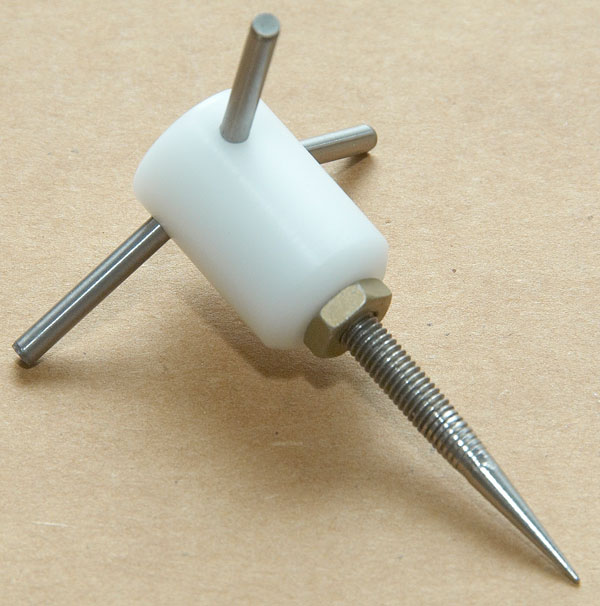
The final piece to make is the central contact bar holder. It is also made from Delrin with three 1/8" (3.17mm) holes drilled at 120 degrees apart. In the holes are pushed three contact pins that will provide the bridge between the balls. I used 1/8" dowel pins and I also tried solid carbide PCB drills shanks. They are very difficult to cut: I used a diamond cutting wheel to nick them and then I broke them off like a piece of glass. The dowel pins are much easier to use. Make sure that they do not short together in the centre when pushed in. The dowel pins in the picture has not been cut yet so they are much too long. Still missing on the center piece are two flats near the end to allow it to be held while attaching the tip. The center is drilled and tapped for a 5mm screw. That allows standard tips to be used. The very crude tip in the picture is just for initial testing while I am waiting for the ordered tips. For example, see the hundreds of tips available from: www.itpstyli.com 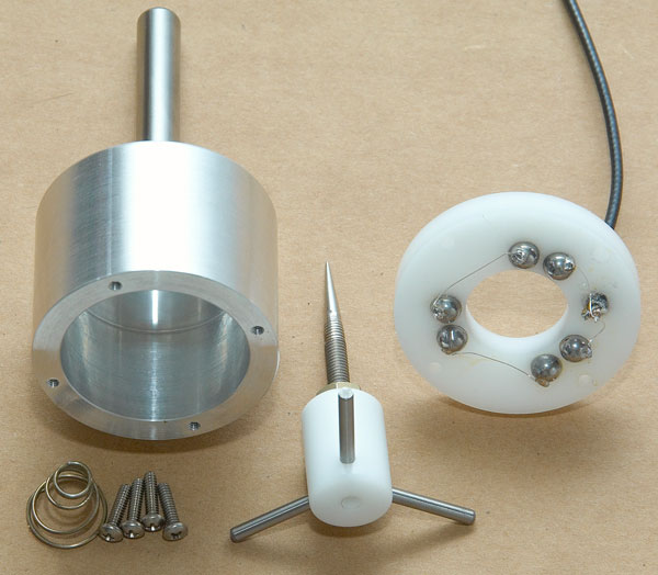
For the final assembly a spring is added inside to provide a pre-load on the pins against the balls and everything is held in place with the four mounting screws. Scan Results:

After a conversion in AccuTrans to a mesh the Quarter looks like this: 
Finally after saving it as an STL file and importing that file into MeshLAB and running a smoothing algorithm, the 3-D model looks like this: 
Software:
Summary:
Engineering consists to a large extent of the requirement to evaluate different approaches and make compromises between them: Adjustability vs. Stability and Simplicity. The reliability of a soldered cable vs. the convenience of being able to unplug the cable and so on. Because all the critical components are on the ball holder plate, it is only one item to change if a different idea is tested. For example, what happens with the contact resistance vs. angular contact point on the balls? The current position is at 50 degrees. (0 is on top of the ball, 90 on the vertical side.) Bertho Boman
|