
For printing with ABS material it is desired to have a heated enclosure to avoid thermal stresses in the plastic.
There are many ways to create an enclosure for the Ultimaker as can be seen on various websites. I wanted something better and here is what I came up to meet my requirements:
Looking reasonably good
Transparent
Instantly removable for full access
Since I wanted the enclosure to be very clear I chose to make it from 5.2mm thick clear Acrylic. The recommended continuous maximum service temperature is listed as 82°C, which sounds low, but even if the inside temperature is much higher the actual plastic temperature will be much lower since it is being cooled by the room temperature air.
As there are many styles of enclosures there are also many ways of actually fabricating an enclosure. I chose to laser cut the different pieces and solvent weld them. An alternative approach to solvent welding would be screws and nuts like the Ultimaker enclosure. Instead of laser cutting the different pieces they can be sawed.
I downloaded the original Ultimaker enclosure laser cutting files from the official Ultimaker website and converted them to AutoCAD drawing format that I then edited to get just the door openings outline. Unfortunately there are several generations of Ultimaker where gradual improvements have been made so some dimensions were not matching my version. After multiple measurements and updating the AutoCAD file to match my Ultimaker, the file was used to generate G-code for the laser cutter and the door panels were cut. My door panels fit flush with the enclosure so they need to have the exact shape of the cutouts.
An easy way to manually achieve that is to place the Acrylic panel with the protective paper still on it on the outside of the door opening and then trace the opening outline from the inside of the enclosure and afterwards carefully saw and sand the panels to match that outline.
The left side stock fan enclosure slightly sticks out a little bit too far but since I am in the process of redesigning the fan enclosure for dual fans that will not be a long-term problem for me. Temporarily I have to close the door after homing at start-up. Alternatively a small extension piece can be added to the block pushing on the left home switch to make it stop a few millimeters earlier.
Doors:
The secret for achieving the instantly removable doors: The hinges! I bought them from McMaster in the USA. Remember to order both left and right side hinges. Magnets keep the doors shut.
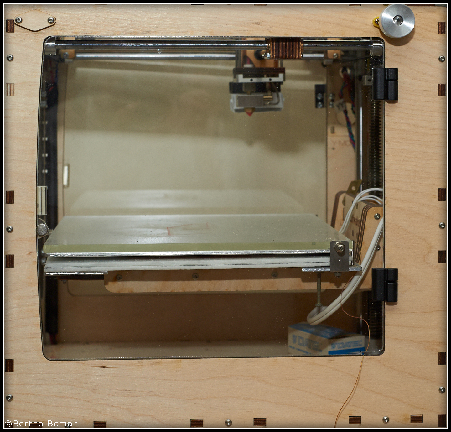
I started to take pictures but quickly found out that it is difficult to show a transparent object. The visible aluminum knobs are drive shaft extensions so I can manually move the head when the power is off without opening the enclosure. It was a “free-be” when I changed the shafts to externally mount the the motors for direct drive. I had to make a cutout section in the door to not hit the knob. http://www.mcmaster.com/#lift-off-hinges/=rh12y3
Top Section:
I take a lot of pictures but it was hard to get good pictures of the top section since it is all clear Acrylic. I really did not have time to temporarily paint it with a water soluble paint for the pictures. Please excuse the so-so pictures.
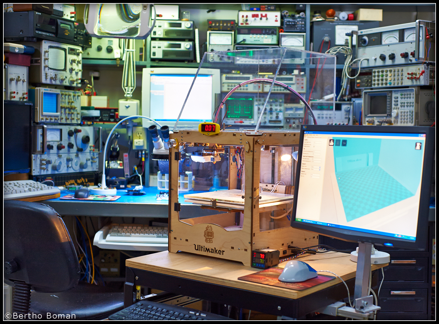 The Ultimaker sits on a desk and the monitor slides out on a bracket and folds away when not used, That is also true for the keyboard. Also seen on the desk is the temperature controller for the heated glass table.
The enclosure just sits on top of the Ultimaker and can instantly be removed. All sides are 90 degrees except the sloping front panel.
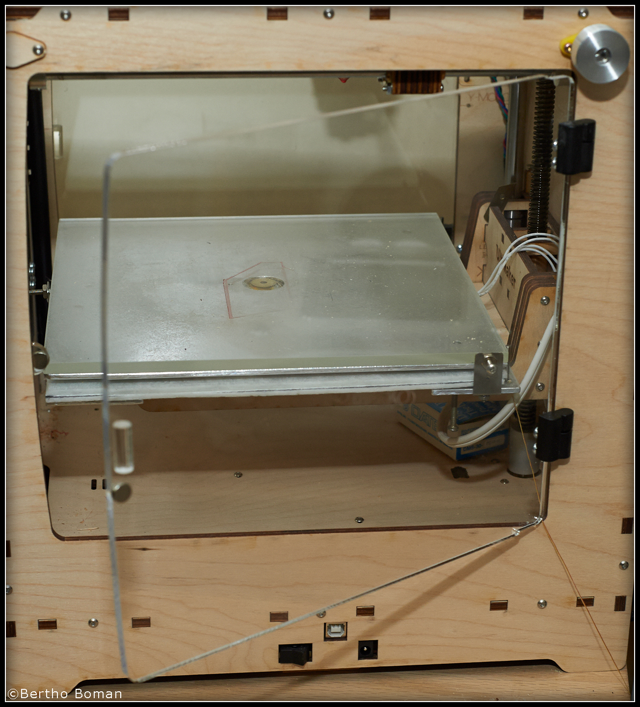
 A closer look from the side. As can be seen, the back of the unit extend just beyond the feeder so the Bowden tube can enter from the bottom, not the back.
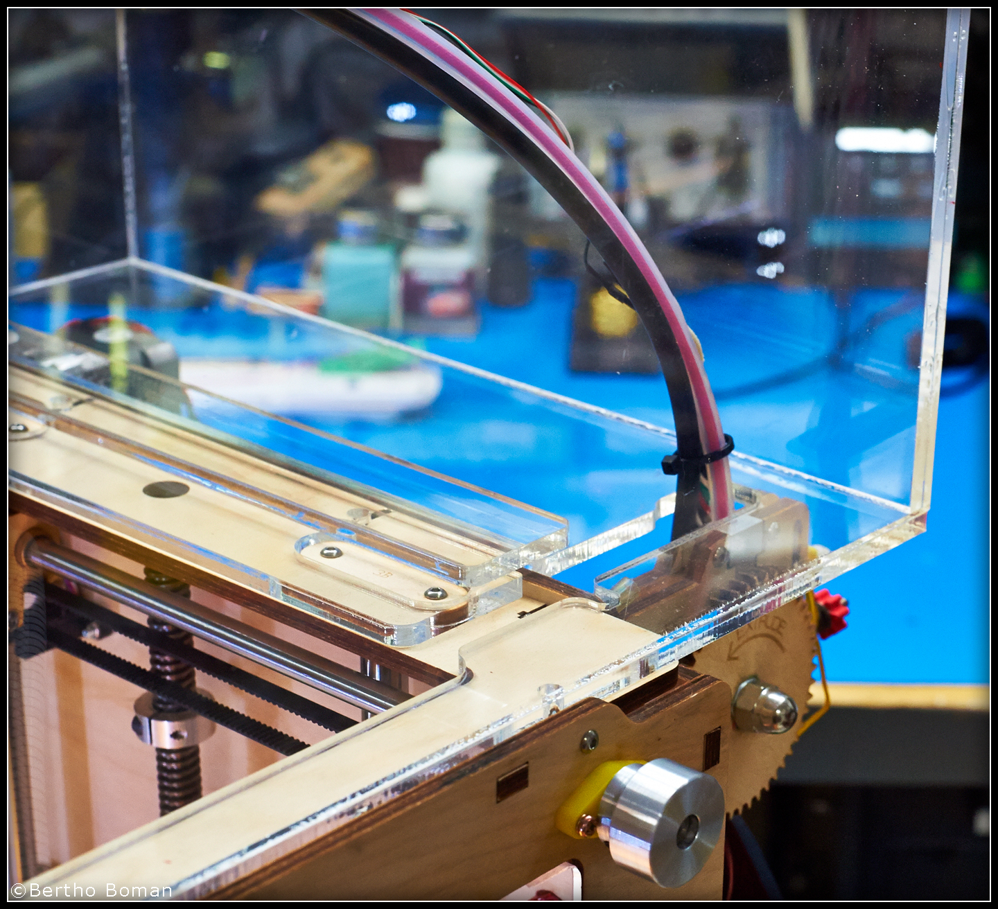
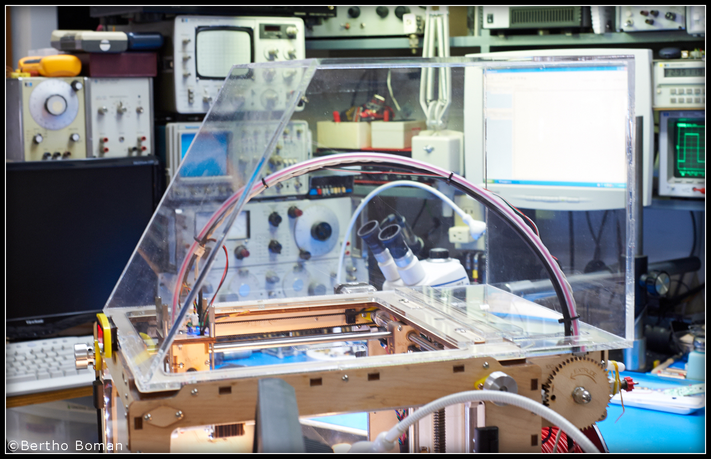
A closeup of the critical slot that allows the instant removal of the top section. The cutouts in the top base section can also be seen to clear various items sticking up above the Ultimaker top panel. Since the long Ultimaker back section almost cuts off the whole back shelf, there is a reinforcement solvent welded across the back edge.
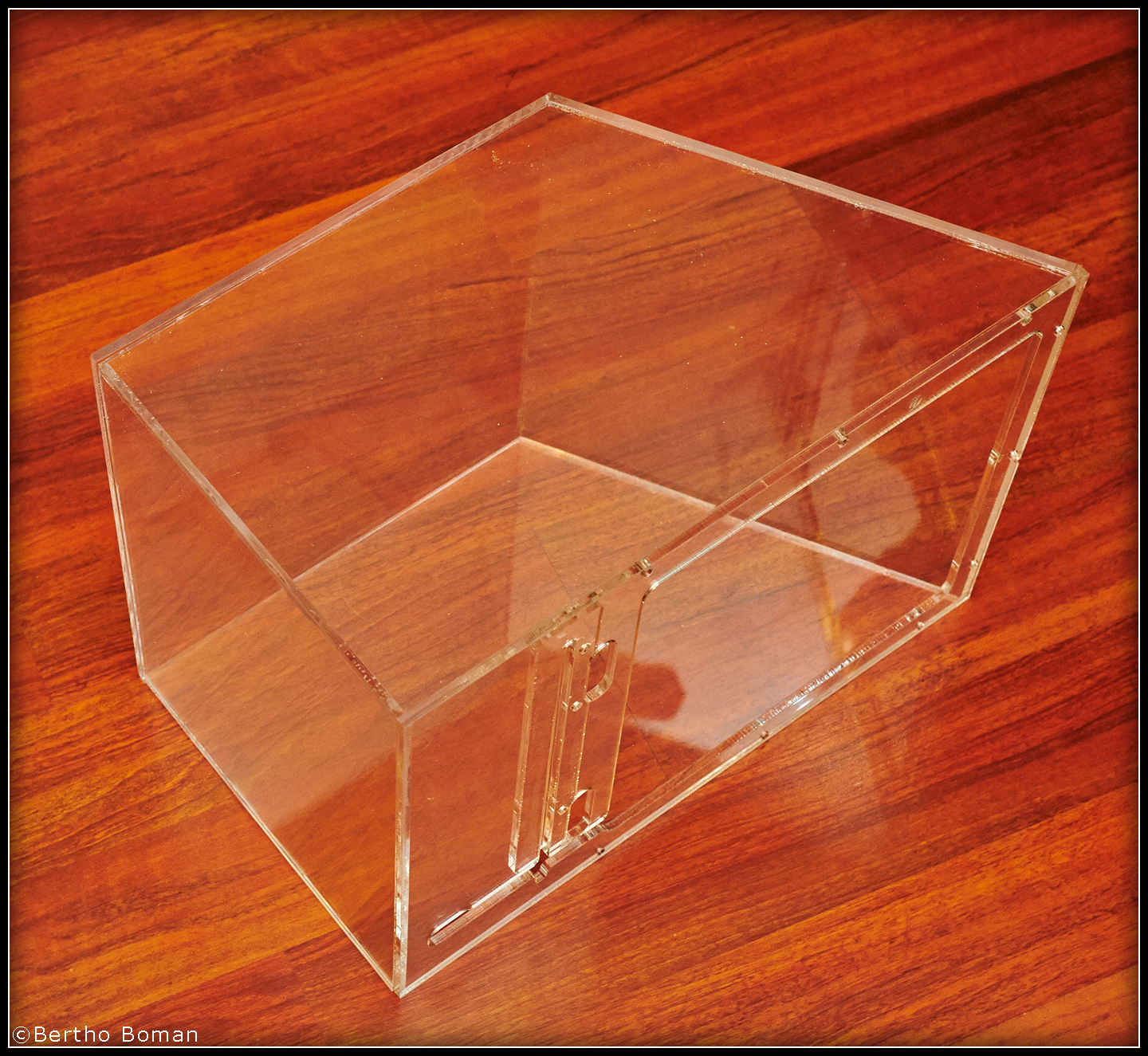 Another view. There are no screws, just solvent welding. The most difficult part is getting the tilted front panel to match with the top panel and the base front edge because the edges have to be cut at an angle to properly fit. See the CAD file. It would be a lot easier to just make a rectangular box without the sloping section.
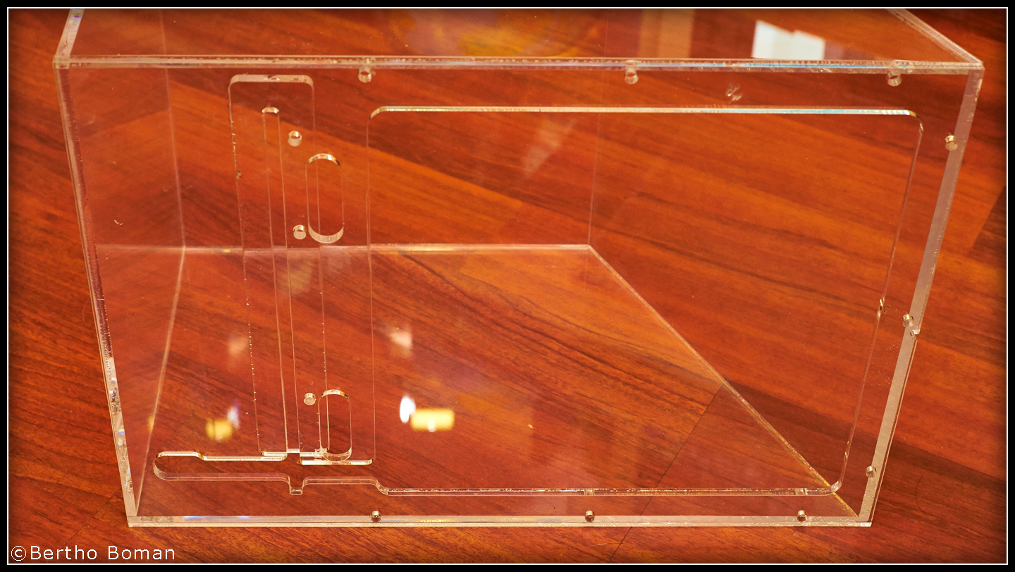 Here is another look. The major cutout can be seen and the Bowden slot is clearly visible.
This writeup is not intended to a construction guide. It is what I did to my Ultimaker and you need to customize and adapt it to your own printer.
Here is a link to my AutoCAD drawing. Most CAD programs can import AutoCAD files.
http://www.Vinland.com/Images/UM_Enclosure.dwg
Heater & Controller:
Soon! At least I got started and got the door and top section information finished.
Great blog here! Also your website loads up fast! What host are you using? Can I get your affiliate link to your host? I wish my website loaded up as fast as yours lol
My hosting company is: https://www.appliedi.net/
Thanks!
The blog is written using WordPress.
The website is hosted on:
Applied Innovations
http://www.appliedi.net
1001 Yamato Road, Suite 300W
Boca Raton, FL 33431
They are very reliable and I have been using them for over a decade.
Bertho
I am wanting to make one of these for my Ultimaker 2. Have you made one with a filter and fan yet? How do you control the temperature inside the enclosure? Would like to have a filter to control the smell/fumes from ABS. Using in a small area.
There is a fan inside the enclosure for the enclosure heater. I have a separate temperature controller for the enclosure. A 200W heater is insufficient, it looks like I need about 500-600W but I have not had time to install it. A filter would be external with a separate VERY weak exhaust system since you do not want to keep sucking in cold air into the enclosure.
Bertho
I have added an internal fan but the fan motor is outside. I have not added any air filter.
I got this web page from my pal who told me on the
topic of this site and now this time I am visiting this web page
and reading very informative articles here.
Good post. I certainly love this site. Continue the good
work!
Wonderful, what a website it is! This webpage gives helpful information to
us, keep it up.