| Home |
| Misc. |
|
1-July-2012 Bertho Boman |
|
|
|
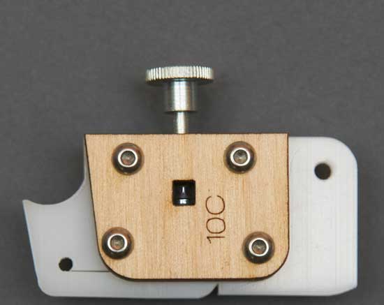
Original Pressure Plate Assembly Introduction
Above is the standard pressure plate assembly used in the Ultimaker 3-D printer. It is laser cut from plywood and from Delrin. It functions reasonably well but has two issues that can be improved.
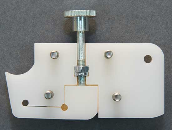
Original Delrin Pressure Plate 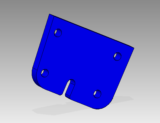
New Side Plate Two identical side plates were printed (or they could be laser cut). Note, the hole spacing has been changed and the part is slightly squared up to be exactly matching with other CAD designed parts. There are very small errors in the original extruder drawings which prevents a real CAD program to properly snap parts together for alignment. 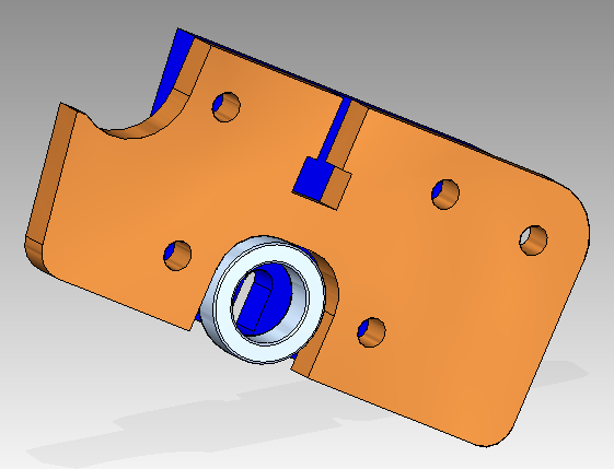
Replacement for the old Delrin Piece This part matches the original size so the new assembly will fit without modifications. It is printed in PLA or ABS. There is no need for the low friction properties of Delrin.
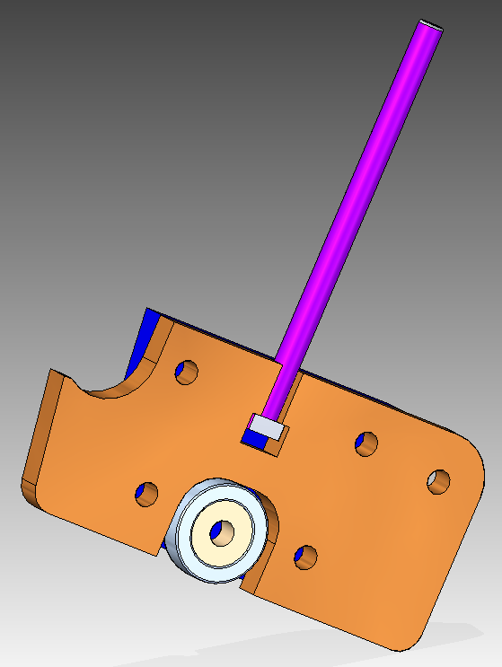
Screw and Bearing Hub added The bearing center hub is slightly wider than the bearing to make sure the bearing outside is not touching the walls.
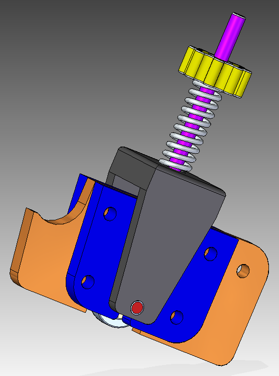
Yoke, Spring and Nut added This is now the finished assembly except missing the regular 3mm screws. A yoke has been added that applies force to the ball bearing shaft. The force is controlled by the spring and adjustment knob. 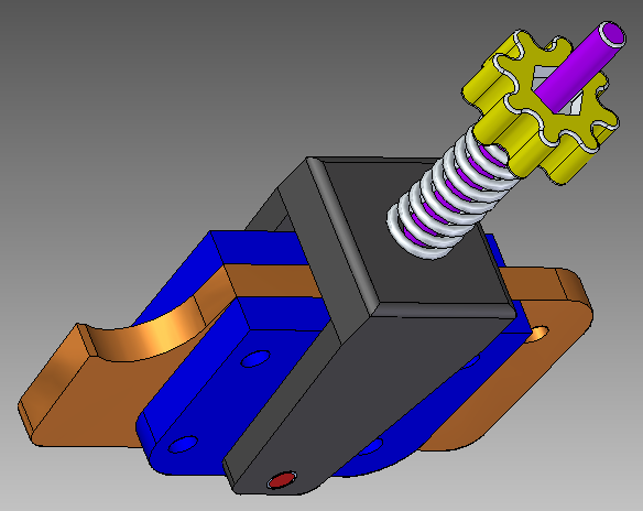
The recess in the knob is visible From this view the recess for a 3mm nut can be seen. The recess was intentionally made to an exact dimension expecting that as usual the hole to be slightly too small. That allowed the nut to after heating be securely pressed into the recess. 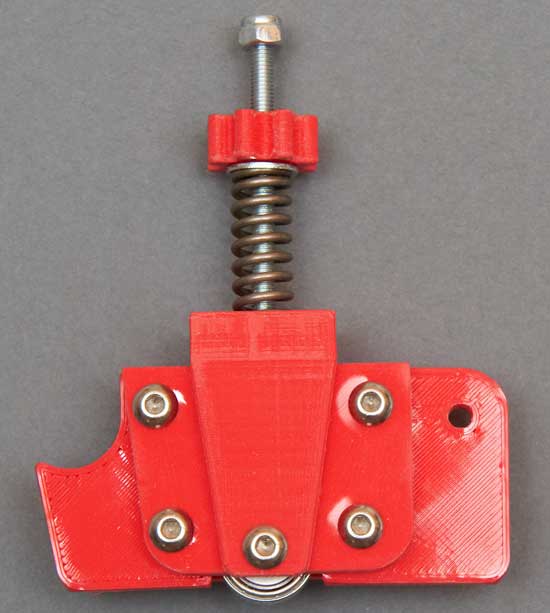
First printed assembly A washer was added between the spring and the knob. Also an "acorn" nut was added to avoid the sharp end of the screw.
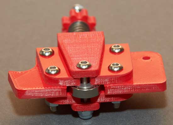
End View 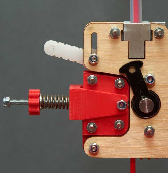
The new assembly inserted into the Ultimaker Extruder Driver In place and functional! The quick release functions as usual except pressure needs to be applied to the assembly while sliding out the little handle. Also visible in this picture is my replacement of the original Bowden tube holder. This design locks the tube rigidly to the extruder driver frame with absolutely no movement. Measurements: 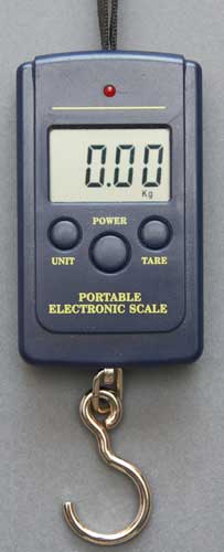
Low-cost digital luggage scale A very useful device to be able to make good measurements is a force scale. The simplest and lowest cost are the luggage scales that can be found at many locations, often for less then $10. I have checked several brands with precision standards and they have been VERY accurate. It is a recommended accessory since it can be used to measure various variables on the 3D printer. I measured my initial setting that I guessed at and it is 3.4 kgf. I have not had time to evaluate and find the ideal setting but that is working fine so far. It is on my to-do-list.... Summary:
Now I have to learn how to properly put up a project on Thingiverse so other users will get a chance to evaluate and try the design. Bertho Boman
|